Component dimension – what exactly is it?
Due to the dimensioning, the relevant manufacturing information is added to the component on the drawing, whereby several points have to be taken into account. The dimensioning clearly defines the geometry of the component by describing the length, width, height, diameter, radius and shape of the component. This is necessary so that the component can be manufactured correctly for the intended use. Sometimes small errors in the dimensioning result in the component not being able to be used. However, some errors are noticed during production and can be clarified directly, but these queries cost unnecessary time on the part of the producer and the client.
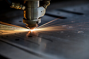
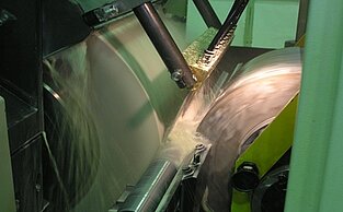
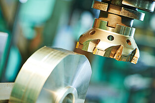
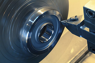
Do you want to find out more about milled or turned parts? Then visit us in the magazine.
If a component is dimensioned on the drawing, then there are different approaches to doing so. In technical drawing, a distinction is made between function-related, production-related and test-related dimensions.
Functional dimensioning focuses on the use of the component and the intended function. After the component is finished, it should function properly. Therefore, the dimensions are entered, selected and tolerated in such a way that the component functions smoothly in the end. At this point, therefore, no consideration is given to the testing or manufacturing of the component, but only the function is in the foreground.
However, if it is a production-related dimensioning, the draughtsman takes into account the manufacturing of the component. He has the possible manufacturing process for the component in mind and therefore adjusts the dimensions for production. The functionality of the component shall not be restricted in this context. Similarly, the manufacturer should not have to convert the dimensions for the production of the component.
The third approach is test-related dimensioning. This approach focuses on the testing of the manufactured component.
One of the basics when drawing technical drawings is the standard of the unit. To ensure that there is a unit below the drawings, it is stipulated that the DIN 406-10 and DIN 406-11 standards should be observed on the drawings. These standard-compliant specifications are important for the realisation of the components.
For a drawing to be complete, the measurement line, measurement number, measurement guide line and measurement arrows must be present. The measurement line describes the dimension, while the measurement number defines the size of the dimension. The gauge line leads from the dimensioned drawing element to the gauge line, thereby delimiting it. The measurement arrows show the end point of the measurement line and thus complete the drawing.
The values, which are given in the form of decimal numbers, are referred to as the ‘nominal measure’. It is important that the nominal dimension also has to be provided with the tolerances and fits. If no additional dimensions are given here, the general tolerance applies. Length measurements may be given without the commonly used unit of measurement (mm).
If there are elements on the drawing that are not represented to scale, then they must be represented as an underlined measure.
For the different drawing elements such as radii, threads, chamfers and boreholes, other fixed rules apply which must be observed.
If there are formula elements on the drawing that repeat at the same distance, then these are represented and measured only once. The other formula elements are represented in a simplified way and indicated by the center line.
If the parts are the same or the individual elements have the same geometric shape, a dimension chain can be used at this point. When specifying the length of dimensional chains, the dimensioning takes place from the inside to the outside.
If a measure is particularly important for a test to be carried out after production (e. g. in case of fits), then a rounded border must be noted around the measure. At this point, the manufacturer knows that the drawing element is of great relevance and should be re-examined after manufacture. This allows the customer to ensure that the components function properly.
Checklist for a component dimension
- Details in DIN 406 standard
- All data available
- Measurement line
- Measurements
- Measurement line
- Measuring arrow
- Indication of tolerances
- Marking of non-scaled elements
- Identify special features such as holes, chamfers, threads and radius
- Mark important value to be checked again after manufacture with a box around the value
If the tolerance is not specified or incorrect, then the component may not be usable for the customer later, despite correct production, because it is not suitable for the intended use. A missing indication, which would result in non-use of the component, would be, for example, if the tolerances are allowed to deviate only in one direction, i. e. only smaller, but not larger.
Errors that occur during production may delay delivery, because missing information must first be requested by the customer and subsequently supplemented. Also typing errors and contradictory information lead to queries or incorrect productions because the error is not detected. For example, incorrect double dimensions or typing errors in the radius can have a major impact on the component and its area of application.
All these errors may result in a loss of function of the component. As a result, it becomes unusable and may have to be re-manufactured at a cost.
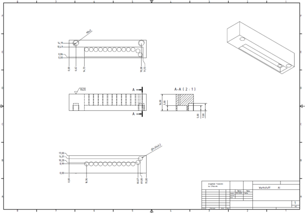
The drawing "Correct Dimensions of a Drawing" contains all important information and dimensions from the text.
The material, the measurement arrows, guides or numbers are present and not duplicate. Errors were deliberately built into the other drawings in order to clarify them and avoid them in the future.
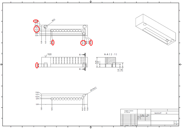
Circles on "Lack of dimension and material"
- missing measurement numbers and measurement lines
- missing material
Orbits on "Repeat of dimensioning"
- Information too much
- double entries
Avoiding such errors simplifies the processing of your request at PART FACTORY.
If all details have been provided, the component can be manufactured by different manufacturers and all supplied components are usable for the intended use.
If the standards are met, there are usually no time-consuming queries from manufacturers and the component meets expectations – if manufactured correctly – and can be used for its intended use.
After submitting the drawing with the request, PART FACTORY checks it for completeness. In case of errors, our qualified staff will contact you in order to be able to correct them quickly and easily.
As a B2B contract manufacturing portal, www. partfactory. com offers high core competence for the production of metallic components and
especially to their contract manufacturing.
We mediate production orders for submitted drawing parts to suitable producers in our qualified network of approved contract manufacturers from all over Europe. These reliable partners produce commissioned components exactly to specification, which we continuously check. Customer data and communication flow exclusively between you and PART FACTORY.


![[Translate to English:] PART FACTORY - Bemaßung von Fertigungszeichnungen [Translate to English:] PART FACTORY - Bemaßung von Fertigungszeichnungen](/fileadmin/_processed_/d/8/csm_Baugruppen_b72ecb4461.png)
![[Translate to English:] PART FACTORY - Bauteile bemaßen [Translate to English:] PART FACTORY - Bauteile bemaßen](/fileadmin/_processed_/2/8/csm_engineer-4054593_1920_310384689c.jpg)
![[Translate to English:] PART FACTORY_ Werkstück mit Bemaßung [Translate to English:] PART FACTORY_ Werkstück mit Bemaßung](/fileadmin/_processed_/5/6/csm_PART_FACTORY__Werkstueck_mit_Bemassung_5fafe75533.jpg)
![[Translate to English:] PART FACTORY_Bauteil bemaßen [Translate to English:] PART FACTORY_Bauteil bemaßen](/fileadmin/_processed_/c/a/csm_PART_FACTORY_Bauteibemassung_41d552714e.jpg)
![PART FACTORY_Lack of dimension and material [Translate to English:] PART FACTORY_Lack of dimension and material](/fileadmin/_processed_/c/3/csm_Fehlende_Bemassung_und_Material_bearbeitet_995bde3c33.png)



![[Translate to English:] PART FACTORY - Kontaktaufnahme [Translate to English:] PART FACTORY - Kontaktaufnahme](/fileadmin/_processed_/2/4/csm_woman-2773007__340_590260e0fe.jpg)

